The point target location is defined by latitude and longitude (in decimal degrees) and elevation (in meters) in the WGS84 geodetic system. If no further description is given in the comments, then the coordinates refer to the scattering center for the current alignment. For a trihedral corner reflector, the coordinates would reference the innermost corner.
Definition of Pointing Angles
The point target pointing angles refer to the direction of the target's principal (dominant) backscattering direction. The direction is defined by two angles described below. Reported target RCS values are valid for this pointing direction.
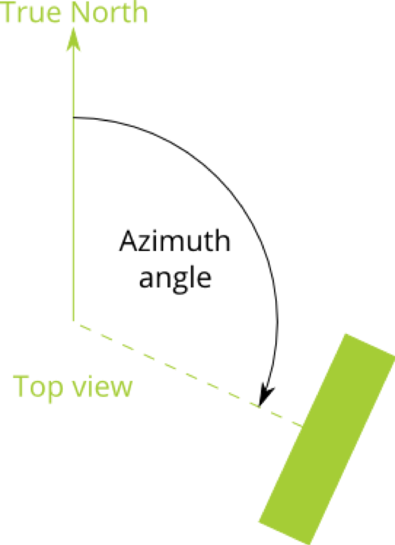
Azimuth Angle
The azimuth angle is defined as the angle formed by the "true north" direction and the target's principal backscatter direction, projected onto the local ground plane. The sign follows the convention of a compass rose, i.e., increasing angles fall together with a clock-wise rotation when seen from above. Examples: An azimuth angle of 0° denotes a target pointing north. An east-pointing target has an azimuth angle of 90°.
Incidence Angle
The incidence angle is defined as the positive angle between the local vertical and the point target's principal direction (direction with peak RCS), expressed in degrees. Examples: An incidence angle of 0° denotes a target which looks vertically up into the sky. An incidence angle of 90°, on the other hand, denotes a target which looks horizontally. Typical angles range from 15° to 60°.
Radar Cross Section (RCS)
The (monostatic) radar cross section is reported in dBm² for the four principal polarization components HH, HV, VH, VV. The first component describes the polarization of the sender, the second the polarization of the receiver. The RCS depends, for most practical point targets, on frequency and incidence angle. The reported cross sections are assumed to be valid for the principal (dominant) backscatter direction. For each target, different radar cross sections depending on frequency might be recorded in the database.
Necessary Information for a New Calibration Site Entry
Please consider sharing information on your SAR calibration sites with the CEOS community! If you do, make sure that you provide all necessary information as stated below and send it to the CEOS-WGCV – SAR Subgroup Chair. The information will then be entered manually to the database.
General Information
The general information on the target group (collection of targets from the same organization) should contain:
Maintainer (contact person, registered on the website).
Contact details (as appropriate, for instance an email address and phone number).
Possibly a link for further information.
Point Targets
For each point target, you should provide the following information:
Target name/ID (unique).
A description (free text field).
(Optional) A photo or supplementary file (e.g. a PDF file).
Location: Short name, latitude, longitude, elevation (optional, all in WGS84), estimated location uncertainty in meter (optional), and a description (optional).
Target alignment (alignment of main backscatter direction): azimuth, incidence angle, time of last update.
(Optional) Bandwidth (start/stop), applicable especially for transponders.
(Optional) Radar cross section (RCS) matrix for the four polarizations HH, HV, VH, VV, per frequency (several rows are possible), including estimated radiometric uncertainty.
Distributed Targets
To describe a distributed target, please provide:
Target name/ID (unique).
A description (free text field).
(Optional) Supplementary file (e.g. a PDF file summarizing target characteristics).
Location: Short name, latitude/longitude pairs (WGS84) which describe the ground polygon.


 The azimuth angle is defined as the angle formed by the "true north" direction and the target's principal backscatter direction, projected onto the local ground plane. The sign follows the convention of a compass rose, i.e., increasing angles fall together with a clock-wise rotation when seen from above. Examples: An azimuth angle of 0° denotes a target pointing north. An east-pointing target has an azimuth angle of 90°.
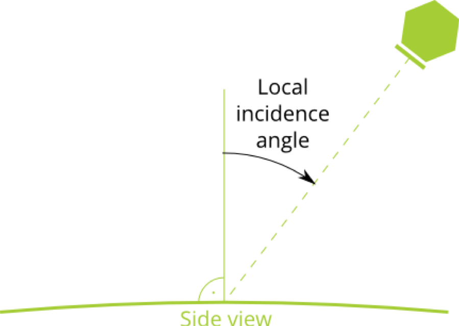 The incidence angle is defined as the positive angle between the local vertical and the point target's principal direction (direction with peak RCS), expressed in degrees. Examples: An incidence angle of 0° denotes a target which looks vertically up into the sky. An incidence angle of 90°, on the other hand, denotes a target which looks horizontally. Typical angles range from 15° to 60°.The (monostatic) radar cross section is reported in dBm² for the four principal polarization components HH, HV, VH, VV. The first component describes the polarization of the sender, the second the polarization of the receiver. The RCS depends, for most practical point targets, on frequency and incidence angle. The reported cross sections are assumed to be valid for the principal (dominant) backscatter direction. For each target, different radar cross sections depending on frequency might be recorded in the database.Please consider sharing information on your SAR calibration sites with the CEOS community! If you do, make sure that you provide all necessary information as stated below and send it to the CEOS-WGCV – SAR Subgroup Chair. The information will then be entered manually to the database.The general information on the target group (collection of targets from the same organization) should contain:
